How to Draw Camera Symbol in Autocad
Insert symbols and details into your drawings from commercial online sources or from your own designs.
Some Basic Definitions
In AutoCAD, symbols and details that you insert into drawings are called blocks. A block is a collection of geometric and text objects plus other data that are combined into a single named object. The following are some examples of a variety of blocks at different scales.
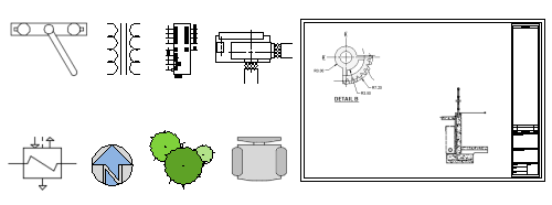
There are four things involved for inserting blocks in a drawing.
- A block definition. This data is stored in a drawing file or drawing template file in a non-graphical format. Block definitions can easily be created or imported from any drawing file.
- A block reference. When you insert a block, you specify a drawing file or a block definition to import. The graphics for the block reference are generated from the block definition.
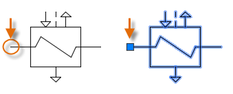
- A block insertion base point or just base point. When you insert a block, this is the part of the block attached to your cursor.
The base point is circled on the block below. Later, if you select a block that's already been inserted, it displays a grip at the base point. You can easily move and rotate this block using this grip.
- A block insertion tool. Several different tools are available in the product. These include the block gallery on the ribbon, the Blocks palette, the Tool Palettes window, and Autodesk Design Center.
For example, the following drawing contains only four block definitions: Cubicle, Chair, Table, and Plant. There are three block references to Cubicle, twelve block references to Chair, two block references to Table, and two block references to Plant.

Considering this example, what are the advantages of inserting the chair as a block reference 12 times rather than creating 12 copies of a geometry of the chair?
- The block reference of the chair associates the geometry of the chair into a single object, which is easier to move, copy, and rotate as a unit.
- The part number, vendor, and other information, which are called block attributes, can be stored with the block definition or each block insertion. This data can be extracted into a schedule or a report.
- If you make a change to the block definition in a drawing, all the associated block references in the drawing are immediately updated.
- For drawings with many repetitive elements, the amount of data stored is significantly less when these elements are stored as block references.
Note: The commonly used term, block, can refer loosely to either a block definition, a block reference, or both depending on the context.
Insert Blocks into a Drawing
Typically, you insert a block into the current drawing from one of these sources:
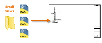
- Any drawing file. For example, you might create a drawing of a standard detail view. You can then use a block insertion tool to insert this drawing as a block into your current drawing. In this example, the detail views folder is commonly termed a block library folder.
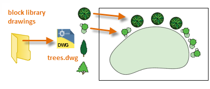
- One or more block definitions contained within a drawing file. For example, you can create a drawing that only contains block definitions of trees. You can then insert any of these blocks from that drawing into your current drawing. A drawing file that contains a family of related blocks is commonly termed a block library drawing.
- One or more block definitions created in your current drawing. For example, you might want to create a block from a set of objects that appear repeatedly in that drawing, such as the following cubicle arrangement that contains multiple nested blocks. All the blocks used in the cubicle arrangement can be combined into a single block for multiple placements.
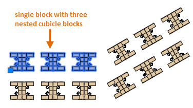
Once you insert a block, you can easily move, copy, rotate or scale it as a single unit.
Use a Block Insertion Tool
To get started with the Blocks palette, follow these steps:
- Click Insert from the Home tab and click Blocks from Libraries. This starts the BLOCKSPALETTE command.
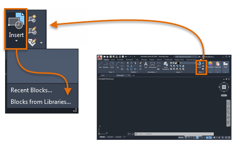
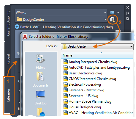
- Click the Browse button to display a folder or file selection dialog box.

- Navigate to the DesignCenter folder where a variety of sample drawings are stored.
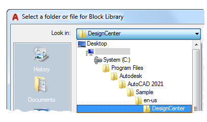
Each drawing in the DesignCenter folder contains a set of related block definitions.
-
Select a drawing file that interests you.
For example, let's say you create drawings for heating, ventilation, and air conditioning. Select the HVAC drawing and then click Open.
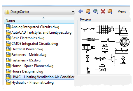
- From the Blocks palette, Libraries tab, click and place several of the blocks.
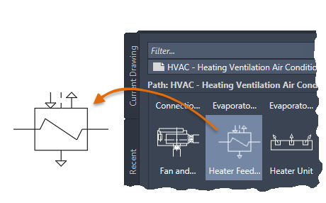
This action copies the selected block definition from the block library drawing into your current drawing and inserts a block reference. Inserting additional block references will now be much faster. To specify a different drawing file, use the Browse control as before.
- To choose a different library drawing from the DesignCenter folder, make sure that the Library tab is the current one (1) and click the file navigation button (2).
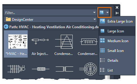
- Experiment with the other controls. For example, try changing the preview control.
This action opens the Blocks palette to the Libraries tab.
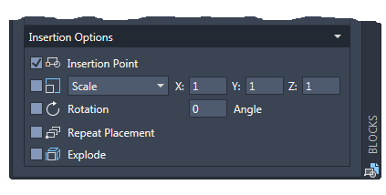
Tip: The default options at the bottom of the Blocks palette are usually acceptable, but you can experiment with them to see what options you might want to use.
Notice that the next time you click Insert on the ribbon, the gallery displays all of the block definitions stored in the current drawing. You can quickly click and place these blocks from the gallery into your drawing.
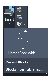
Also, familiarize yourself with the Blocks palette by clicking on the Current Drawing tab and the Recent tab.
- The Current Drawing tab displays all of the block definitions in the current drawing only.
- The Recent tab displays the block definitions that you've recently inserted or created in the current and previous sessions. These blocks can come from various drawings.
Create a Drawing for Use as a Block
Often, individual drawing files are created to be used as blocks and saved in a folder with similar drawing files. This method is an alternative to accessing the block definitions stored in a single drawing.
When you create a drawing file for use as a block, make sure that you locate an object at the origin point (0,0). This will serve as the default base point of the block. Later, when you insert the block, it is attached to your cursor at the base point.
In the following example, a drawing file is inserted into the current drawing to provide a standard detail view.
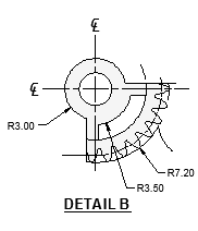
Custom title blocks and drawing borders are also created as drawing files that can be inserted later or included in drawing template files.
Tip: When you save drawings for later insertion, navigate to a folder, right-click, and create several folders to organize the drawings. You can drag one or more of them into your Places bar for easier access in the future.
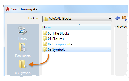
Manage Block Definitions and Data in a Drawing (Optional)
You can create, remove, and modify block definitions directly in the current drawing for special circumstances.
- Remove unused block definitions from a drawing with the PURGE command. Purging a drawing of unused block definitions can reduce the size of a drawing. You can purge only those block definitions that aren't used by any block references in the drawing.
- Create new block definitions directly in the current drawing with the BLOCK command. Creating block definitions is useful either if you need a block that's unique to that drawing or if you want to create a block library drawing that contains a family of related block definitions.
- Disassemble a block reference into its constituent objects with the EXPLODE command. Exploding block references provides an easy way to define new versions of a block definition with the BLOCK command or to save the resulting objects to a new drawing file with the WBLOCK command.
Tip: Block definitions can also include objects called block attributes that can store information such as part number, vendor name, and cost. You can extract and export block attribute data to a table, schedule, or external file. Some blocks called dynamic blocks can change their appearance dynamically depending on the associated data, location, or options chosen.
Summary of Suggestions and Recommendations
Several different methods are commonly used for saving and organizing block definitions.
- Create an individual drawing file for each block that you intend to use. Save these drawing files in folders that contain families of related drawing files.
- Create drawing files called block library drawings. Each one of these drawings contains a family of related block definitions. When you insert a block library drawing into your current drawing, all the blocks that are defined in that drawing become available in your current drawing.
- Include the block definitions for title blocks and commonly used symbols in your drawing template files to make them available immediately when starting a new drawing.
- Evaluate which block insertion tool best suits your needs: the Blocks palette and ribbon gallery, the Tool Palettes window, or Autodesk DesignCenter.
Tip: With online access, you can download AutoCAD drawing files from the web sites of commercial vendors and suppliers. This option can save you a significant amount of time, but always check to make sure that these drawings are drawn correctly and to scale.
Source: https://knowledge.autodesk.com/support/autocad/learn-explore/caas/CloudHelp/cloudhelp/2021/ENU/AutoCAD-GettingStarted/files/GUID-2DA2ADA1-C8CC-4E61-9598-06580FFD3544-htm.html
0 Response to "How to Draw Camera Symbol in Autocad"
Post a Comment